

Power Electronics Blog & Knowledge Base
Discover in-depth technical analysis, design considerations, and updates on industrial power supply solutions.
Choosing a reliable Non Isolated SIP SMD DC DC Converter requires more than comparing price and output voltage. Buyers must examine efficiency, input range, load regulation, ripple, thermal behavior, and package compatibility. A compact SIP SMD device may fit neatly beside a microcontroller, yet still produce excessive heat under continuous load. That detail matters in real equipment.
Experienced engineers usually begin with the power budget. They check startup behavior, switching frequency, protection functions, and derating information. They also compare verified test conditions, because advertised performance can change with temperature or load. Small differences become important.
Look closely.
A dependable supplier should provide clear datasheets, traceable specifications, and responsive technical support. Independent testing, recognized quality systems, and consistent production records can strengthen purchasing confidence. However, certification marks alone do not guarantee suitability for every design. Board layout, airflow, grounding, and capacitor selection still influence results.
This guide reviews leading non-isolated SIP SMD DC-DC converters from a buyer’s perspective. It considers practical selection factors, including installation space, operating temperature, electromagnetic performance, and long-term reliability. Some products may appear excellent on paper but perform differently in a crowded enclosure. That is a limitation worth acknowledging.
The best choice balances electrical performance, mechanical fit, supplier credibility, and total ownership cost. Careful comparison can prevent unstable outputs, unnecessary redesigns, and avoidable field failures. There is no universal winner. The right converter depends on the application, and that judgment deserves evidence rather than assumptions.
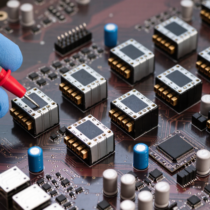
Classify Non-Isolated SIP SMD Converters: Buck, Boost, and Buck-Boost
Top Non-Isolated SIP SMD DC-DC Converters for Buyers?
Non-isolated SIP SMD converters share a direct ground path between input and output. Their compact package suits industrial controllers, sensors, and embedded boards. A 2024 MarketsandMarkets report forecasts the global DC-DC converter market to exceed US$22 billion by 2028. This growth reflects rising demand for efficient, board-level power conversion.
Buck converters reduce voltage. Choose one when the input stays above the required output, such as converting 24 V to 5 V. They usually offer strong efficiency and lower heat. Boost converters raise voltage, such as producing 12 V from a 5 V rail. Their input current can become substantial. Buck-boost converters handle input voltage above or below the target. They fit battery systems where voltage changes during discharge. However, their switching behavior may create more ripple and control complexity. The classification is useful, but not flawless. Real designs depend on load transients, duty cycle, and thermal limits.
Tips: Check the full input range, not the nominal value. Compare efficiency at your actual load. Review ripple, switching frequency, derating curves, and maximum ambient temperature. A 2 A rating may not remain realistic inside a sealed enclosure. Measure the prototype. Datasheet figures often use ideal airflow and short connections. For SIP SMD selection, also confirm footprint clearance, solder-temperature limits, and capacitor requirements. A neat datasheet is not enough.
Top Non-Isolated SIP SMD DC-DC Converters for Buyers: Classify Non-Isolated SIP SMD Converters — Buck, Boost, and Buck-Boost
| Converter Class | Typical Input Voltage | Typical Output Voltage | Voltage Relationship | Typical Output Current | Typical Efficiency | Output Polarity | Recommended Applications |
|---|---|---|---|---|---|---|---|
| Buck Converter | 4.5–36 V DC | 0.8–30 V DC | VOUT is lower than VIN | 0.5–5 A | 85–96% | Usually non-inverting | Logic rails, embedded systems, sensors, industrial control, point-of-load regulation |
| Boost Converter | 2.5–24 V DC | 5–48 V DC | VOUT is higher than VIN | 0.2–3 A | 80–94% | Usually non-inverting | Battery-powered equipment, LED drivers, display backlighting, sensor excitation and USB power rails |
| Buck-Boost Converter | 2.5–36 V DC | 3.3–36 V DC | VOUT may be lower than, equal to, or higher than VIN | 0.3–4 A | 78–94% | Non-inverting or inverting, depending on topology | Single-cell batteries, automotive electronics, portable instruments and unstable input-voltage systems |
Buyer-Oriented Comparison of Non-Isolated SIP SMD Converter Features
| Selection Dimension | Buck | Boost | Buck-Boost | Buyer Guidance |
|---|---|---|---|---|
| Best input condition | Input remains above the required output | Input remains below the required output | Input can cross the required output | Compare the complete minimum, nominal and maximum input range with the output setting. |
| Main efficiency advantage | Very efficient for moderate step-down ratios | Efficient step-up conversion at moderate load | One converter handles both step-up and step-down operation | Use the efficiency curve at the actual input voltage and load rather than the peak rating alone. |
| Typical thermal concern | High current at low output voltage | Higher switch and diode stress at high output voltage | Higher component stress near the transition between modes | Check derating, thermal resistance, airflow and PCB copper area. |
| Typical output ripple | 20–100 mVp-p | 30–150 mVp-p | 40–200 mVp-p | Values depend on switching frequency, load, layout and external capacitors. |
| Control modes commonly available | PWM, pulse-skipping, forced-PWM | PWM, pulse-skipping, current-mode control | PWM, pulse-frequency modulation, four-switch control | Select the mode according to standby current, EMI and transient-response requirements. |
| Common protection functions | Overcurrent, thermal shutdown, undervoltage lockout | Overcurrent, thermal shutdown, overvoltage control | Overcurrent, thermal shutdown, input undervoltage lockout | Confirm whether short-circuit protection is latch-off, hiccup or continuous restart. |
| SIP SMD package considerations | Compact footprint and simple surface-mount assembly | Check inductor and diode clearance around the package | Allow additional copper area for heat spreading and current paths | Verify package dimensions, pin pitch, land pattern, height and reflow temperature limits. |
Note: The electrical ranges shown are representative design ranges for non-isolated SIP SMD converter modules and should be verified against the applicable datasheet, operating temperature, load profile and PCB layout before purchase.
FAQS
No. It is a boundary, not a comfortable target. Aim below 100–110°C when ambient conditions are uncertain.
A converter dissipating 0.8 W with 50°C/W resistance rises 40°C above ambient. At 85°C ambient, the junction reaches about 125°C. That leaves no margin.
Yes. A 30°C/W thermal path may reduce the junction to approximately 109°C. Airflow blockage or thinner copper can still raise temperatures.
Test the actual PCB, not only an evaluation board. Measure near the package with a thermocouple. Confirm results using infrared imaging.
Yes. Derate output current above 60°C ambient. Repeat testing at minimum input voltage. Connector losses can also increase heating.
Request safety reports, insulation data, temperature derating curves, EMC test conditions, and production traceability. RoHS documents should identify restricted substances by material.
No. A laboratory pass may not represent a dense enclosure. Check cable lengths, load levels, layout guidance, conducted emissions, radiated emissions, and immunity results.
Not automatically. Verify the qualified controller, temperature grade, reliability testing, thermal cycling, PPAP support, and lot traceability. The statement may look complete, but it can miss startup behavior.
Review results at 25°C, 70°C, and 85°C ambient. Airflow conditions must be documented. My first estimate was too optimistic because connector losses were ignored.
No. Check switching loss, load current, measured temperatures, and ripple together. A small ripple increase may reveal rising losses. Efficiency can mislead.
Conclusion
Choosing the right Non Isolated SIP SMD DC DC Converter requires a clear understanding of application requirements and operating conditions. Buyers should first classify the converter as buck, boost, or buck-boost according to whether the output voltage must be lower, higher, or flexible relative to the input. Key comparison factors include efficiency in the 90–96% range, rated output current, voltage ripple, and stable operation across input and output requirements from 4.5 V to 60 V.
Thermal performance is equally important, especially when designs approach a 125°C junction-temperature limit. Buyers should review derating curves, airflow assumptions, PCB layout guidance, and continuous-load behavior before selection. Reliability and market suitability also depend on verifying IEC 62368-1 safety considerations, electromagnetic compatibility requirements, RoHS status, and available AEC-Q100-qualified options for demanding automotive environments. A balanced evaluation of electrical performance, thermal margins, compliance, and long-term reliability will support a more suitable converter choice.