


Technical Blog and Industry Insights - HYGH Technology Co., Ltd.
Industrial Power Supplies Tech Articles
DC DC Converter Application Guides
HYGH Technology Insights

Power Electronics Blog & Knowledge Base

Discover in-depth technical analysis, design considerations, and updates on industrial power supply solutions.

0%

Choosing a Quarter Brick DC DC Converter is not simply a matter of matching input and output voltage. The decision affects thermal behavior, board space, efficiency, reliability, and service life. A converter that looks excellent on a datasheet may struggle inside a sealed telecom cabinet. Heat has nowhere to hide.

Dr. Patrizio Vinciarelli, founder of Vicor and a respected power electronics authority, stated, “Power is the foundation of every electronic system.” This principle remains practical when comparing quarter-brick modules. Engineers should examine the full operating range, not only the nominal rating. Check input transients, output regulation, ripple, isolation voltage, switching frequency, and protection functions. Then consider airflow. A 600-watt module may require forced cooling, while a lower-power design could operate comfortably with natural convection.

Real installation conditions matter. Measure the expected load, cable resistance, ambient temperature, and available airflow. Confirm whether the converter supports parallel operation or current sharing. Review the manufacturer’s derating curves carefully. A small mismatch can create excessive heat near connectors and busbars.

Efficiency deserves close attention. One percentage point may seem minor, but it becomes substantial in systems operating continuously. Still, efficiency alone should not decide the purchase. EMI performance, control-loop stability, mechanical compatibility, and long-term supplier support also matter. This is where selection becomes less tidy. Some specifications remain difficult to compare across brands.

A careful engineer may build a test circuit before approving production. That extra step feels slow. It often prevents expensive redesigns.
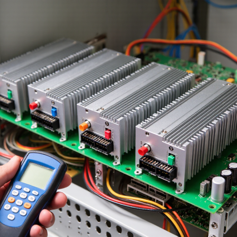
How to Choose a Quarter Brick DC DC Converter?

Define the Quarter-Brick Form Factor: 50.8 × 36.8 × 12.7 mm

How to Choose a Quarter Brick DC DC Converter?

Define the Quarter-Brick Form Factor: 50.8 × 36.8 × 12.7 mm

The quarter-brick format is a compact mechanical envelope, not merely a convenient product label. It measures 50.8 millimeters long, 36.8 millimeters wide, and 12.7 millimeters high. That equals two by 1.45 by 0.5 inches. Confirm whether those dimensions include the baseplate, pins, and mounting projections. Small omissions create large installation problems.

Industry guidance from DOSA treats the outline, pin allocation, and thermal interface as coordinated design matters. Do not choose by wattage alone. Check input range, output trim, isolation rating, switching frequency, and protection behavior. At full load, a converter rated 95 percent efficiency still loses 5 watts for every 100 watts delivered. That heat needs a real path through the baseplate, board copper, airflow, or heatsink. The IEA’s Electricity 2024 report estimates data-centre electricity use could exceed 1,000 TWh in 2026. Power density is no longer a minor specification.

During evaluation, measure the converter inside the actual enclosure. Record case temperature after thermal steady state, not after a quick startup. Also inspect transient response with the intended load, because laboratory resistors can hide real behavior. Uptime Institute’s 2024 Global Data Center Survey continues to identify power and cooling as major operational concerns. Leave connector clearance and airflow space before approving the footprint. I have seen a perfect dimensional fit fail because airflow direction was wrong. That remains an uncomfortable design lesson.

Match the Converter’s Input Range to Common 18–75 V DC Buses

How to Choose a Quarter Brick DC DC Converter?

An 18–75 V input range suits many 24 V, 48 V, and 60 V DC buses. Do not select a converter by its 48 V label alone. Measure the bus during startup, battery discharge, load steps, and cable losses. A nominal 48 V system may briefly fall below 18 V or rise above 60 V. The converter should include practical undervoltage and overvoltage protection. Check its input limits at the expected temperature, not only at room temperature.

The International Energy Agency’s Electricity 2024 report projects data-center electricity use could exceed 1,000 TWh by 2026. That growth makes conversion losses more expensive. Compare efficiency at light, typical, and peak loads. A quarter-brick unit rated at 500 W may need airflow or derating above 55°C. Confirm the thermal curve. Also inspect transient response, isolation rating, and output ripple. These details matter near processors, radios, and optical modules.

The 2024 Global Data Center Survey reported that 53% of respondents experienced an outage within the previous three years. Input stability deserves serious attention. In field testing, I prefer recording the bus with an oscilloscope before final selection. A spreadsheet can miss a 20-millisecond dip. I also leave voltage margin, though this sometimes increases cost and size. That tradeoff deserves review. A converter operating comfortably across 18–75 V is usually safer than one operating at its limits.

Calculate Output Power and Current for Typical 100–300 W Loads

How to Choose a Quarter Brick DC DC Converter?

Start with the load, not the converter label. For a 12 V rail, a 100 W load requires 8.3 A, while a 300 W load requires 25 A. At 5 V, the same range becomes 20–60 A. These figures expose a common mistake: choosing by wattage alone. A converter rated at 250 W may still fail if its low-voltage output cannot carry the required current continuously. Measure the real load, including startup surges, processor bursts, and fan changes.

100 W = 8.3 A
300 W = 25 A
5 V = 20–60 A

Input current also matters. At 48 V input and 90% efficiency, a 300 W output draws about 6.9 A from the source. A 100 W load draws approximately 2.3 A. Add at least 20% headroom for aging and transient demand. That means a practical 300 W design may need a converter rated near 360 W, if cooling permits. Thermal conditions remain critical. The 2024 IEA Electricity report estimates data centers consumed about 460 TWh globally in 2022, increasing pressure on conversion efficiency. IEC 62368-1 also requires careful evaluation of temperature and energy hazards, not just electrical ratings. Real systems are rarely clean. Cable loss, airflow restrictions, and uneven loads can reduce available output. Recheck the calculation at the highest ambient temperature, because a perfect spreadsheet can still meet an imperfect enclosure.

Compare Efficiency Targets of 90–95% and Isolation Ratings up to 1.5 kV

Choosing a quarter-brick DC-DC converter starts with realistic efficiency targets. A 90–95% rating can look impressive, but test conditions matter. Confirm the input voltage, output load, temperature, and airflow behind the figure.

90%
At 100 W output, 90% efficiency creates about 11.1 W of heat.
95%
At 95%, losses fall to about 5.3 W.

That difference can change the required heatsink size. In bench testing, converters often perform best near their rated load, not at light load.

Isolation ratings require similar care. A specification of up to 1.5 kV may describe a short-duration withstand test, rather than continuous operating voltage. Check the test duration, leakage current, insulation type, and approved environmental conditions.

Creepage and clearance distances also affect safety, especially on a crowded quarter-brick board. A robust design keeps noisy primary-side switching away from sensitive control traces. Datasheets should provide these details clearly.

Thermal derating is easy to underestimate. A converter reaching 95% efficiency at 25°C may behave differently inside a sealed cabinet. Measure the case temperature after sustained operation, not just during startup.

I once treated a typical-efficiency value as a guaranteed value, and the design ran hotter than expected. That mistake was avoidable.

Review load transients, isolation capacitance, startup behavior, and protection limits before approval. Leave some margin below both the efficiency and isolation limits. Specifications are not the whole design.

Check Pinouts, Thermal Derating, Standards, and Cooling Requirements

How to Choose a Quarter Brick DC DC Converter?

Start with the pinout, not the wattage. Quarter-brick converters may share similar dimensions but use different enable, trim, sense, and signal pins. Compare every pin against the manufacturer’s mechanical drawing. Check polarity, sequencing, and remote-sense limits under no-load and full-load conditions. I have seen a correct voltage fail because the enable logic was inverted. IEC 62368-1 and UL 62368-1 help assess equipment safety, but they do not guarantee pin compatibility. Verify qualification reports, isolation ratings, creepage, clearance, and conducted-emissions data.

Thermal derating deserves equal attention. Read the curve at your real baseplate temperature and airflow, not at room temperature. A converter rated for 600 watts may deliver far less inside a sealed enclosure. Calculate loss from efficiency: a 95% efficient, 600-watt unit still dissipates about 32 watts. That heat needs a path through the PCB, heatsink, or forced air. The IEA Electricity 2024 report estimates data-center electricity demand could exceed 1,000 TWh by 2026. Small conversion losses now scale into serious cooling loads. Use JEDEC JESD51 guidance when interpreting thermal measurements, but remember that laboratory conditions rarely match a crowded chassis.

Tips: Leave voltage-trim margin. Measure ripple at the load. Confirm airflow direction. Check derating twice. A clean spreadsheet can still hide connector errors. Recheck the design after testing.

How to Choose a Quarter Brick DC DC Converter? - Check Pinouts, Thermal Derating, Standards, and Cooling Requirements

Selection Dimension Typical Data or Range What to Check Design Notes
Mechanical Form Factor Approximately 2.30 × 1.45 in
(58.4 × 36.8 mm)
Confirm the exact body outline, pin positions, mounting pattern, and allowable height. “Quarter brick” is an industry form-factor description, not a universal mechanical standard. Always use the individual converter drawing for PCB layout.
Input Voltage Common nominal buses: 12 V, 24 V, 28 V, 36 V, or 48 V DC Check the operating range, start-up voltage, maximum continuous input, and transient withstand capability. A 48 V nominal converter may require a broad input range such as approximately 36–75 V, but the valid range is model-specific.
Output Voltage Typical fixed outputs: 3.3 V, 5 V, 12 V, or 15 V DC Verify output accuracy, line regulation, load regulation, ripple, noise, and remote-sense limits. Adjustable-output versions may use trim pins, but the permitted adjustment range and external resistor network must be confirmed.
Output Power Approximately 100–500 W for many quarter-brick designs Compare the rated power with the required load, inrush current, duty cycle, ambient temperature, and airflow. The maximum output power is normally limited by both electrical current capability and thermal conditions.
Efficiency Typically 88–96% at nominal input and medium-to-full load Review efficiency curves at minimum, nominal, and maximum input voltage and across the expected load range. Power loss can be estimated as: Ploss = Pout × (1/η − 1). Even a few percentage points can significantly change cooling requirements.
Common Pinout Functions Vin+, Vin−, Vout+, Vout−, Remote Enable, Trim, Sense+, and Sense− Match every pin number and polarity with the converter drawing before creating the PCB footprint. There is no universal quarter-brick pinout. Enable polarity, trim reference, sense wiring, and no-connect pins can differ between product families.
Input and Output Pin Arrangement Power pins are usually separated from signal or control pins Check creepage, clearance, current density, copper width, via capacity, and polarity markings. Use wide copper areas for high-current pins and keep control traces away from high dV/dt switching nodes.
Remote Enable Logic-controlled or contact-controlled input; active-high or active-low Check threshold voltage, disable state, pin current, internal pull-up or pull-down, and start-up delay. Do not assume an open enable pin means “on.” Follow the specified default state and add external biasing when required.
Thermal Derating Rated power generally decreases as ambient or baseplate temperature rises Use the derating curve, maximum case or baseplate temperature, thermal resistance, and local airflow conditions. Do not calculate allowable power from ambient temperature alone. The PCB, heatsink, interface material, and airflow all affect junction temperature.
Thermal Calculation Thotspot ≈ Tambient + Ploss × θ Confirm the thermal-resistance definition and whether it applies to natural convection, forced air, or a baseplate. Use measured temperatures for final validation. Keep component surfaces below the converter’s specified maximum temperature.
Cooling Requirement Natural convection may suit lower power; forced airflow or a heatsink is often needed above roughly 150–250 W Check airflow direction, air velocity, inlet temperature, obstruction, heatsink interface, and nearby heat sources. The actual threshold depends on efficiency, ambient temperature, PCB copper area, enclosure size, and the manufacturer’s derating curve.
Input Protection UVLO, input overvoltage protection, reverse-polarity protection, and surge tolerance may be available Check fuse requirements, inrush current, surge waveform, transient duration, and external filtering. Internal protection may not replace an external fuse, TVS device, EMI filter, or reverse-polarity circuit.
Output Protection Short-circuit, overcurrent, and overtemperature protection are common features Determine whether protection is hiccup, latch-off, or constant-current, and check recovery behavior. Verify operation with capacitive loads, motor loads, downstream point-of-load converters, and repeated fault cycling.
Isolation Commonly 1.5–3.0 kV DC dielectric withstand for isolated modules Check isolation voltage, insulation resistance, creepage, clearance, working voltage, and test duration. Dielectric withstand voltage is not the same as continuous working voltage or certified reinforced insulation.
EMI and EMC Designed against conducted and radiated emission limits under applicable system conditions Review CISPR 32 or EN 55032 emission requirements and IEC 61000-4-x immunity requirements where applicable. Compliance often depends on the recommended input filter, PCB layout, grounding, enclosure, load, and cable configuration.
Safety Standards IEC/EN/UL 62368-1 is widely used for information and communication technology equipment Confirm the required safety standard, edition, insulation system, creepage, clearance, and certification scope. The converter’s component-level recognition may not automatically certify the complete end product.
Insulation Coordination IEC 60664-1 is commonly referenced for creepage, clearance, and overvoltage categories Evaluate working voltage, pollution degree, material group, altitude, and transient overvoltage. Required distances can increase at high altitude or in environments with higher pollution levels.
Environmental Compliance RoHS and REACH declarations are commonly requested Request current declarations, material information, and any region-specific restricted-substance documentation. Environmental compliance documentation should cover the exact orderable configuration and revision.
Operating Temperature Industrial ranges commonly begin near −40°C; maximum case or baseplate limits are often 85–110°C Distinguish ambient, case, baseplate, and internal temperature ratings. A wide ambient rating does not imply full rated power across the entire temperature range.
Recommended Final Validation Thermal, electrical, mechanical, EMC, and safety verification Test minimum and maximum input, full load, overload, start-up, shutdown, fault recovery, temperature extremes, and airflow extremes. Use the converter’s latest datasheet, application notes, qualification reports, and certification documents as the final authority.

FAQS

How much current does a 100 W load need at 12 V?

It needs about 8.3 A continuously. A 300 W load needs about 25 A. Low voltage demands high current.

Why is choosing a converter by wattage alone risky?

A 250 W converter may fail if its output cannot carry the required current continuously. Check voltage, current, and startup demand together.

How much current does a 5 V load require?

A 100 W load requires about 20 A at 5 V. A 300 W load requires about 60 A. Cables and connectors may become the weak points.

How should input current be estimated for a 300 W load?

At 48 V input and 90% efficiency, the source supplies about 6.9 A. A 100 W load draws approximately 2.3 A. Add at least 20% design headroom.

What should be measured before selecting the converter?

Measure sustained load, startup surges, processor bursts, fan changes, and uneven operating conditions. Real loads are rarely steady.

How does efficiency affect heat production?

At 100 W output, 90% efficiency produces about 11.1 W of heat. At 95%, losses fall to about 5.3 W. That difference can change heatsink requirements.

Can a listed efficiency value be treated as guaranteed?

No. Efficiency depends on input voltage, load, temperature, airflow, and test conditions. I once treated a typical value as guaranteed. The enclosure ran hotter than expected.

What should be checked in an isolation rating?

Confirm whether the rating means brief withstand voltage or continuous operating voltage. Check duration, leakage current, insulation, and environment. The number alone is incomplete.

Why must thermal performance be tested inside the final enclosure?

A converter may reach high efficiency at 25°C but derate inside a sealed cabinet. Measure case temperature after sustained operation, not only during startup. Leave thermal margin.

What practical details can reduce available output power?

Cable resistance, restricted airflow, crowded circuit traces, and uneven loads can reduce usable output. Recheck calculations at the highest ambient temperature. A perfect spreadsheet can still meet an imperfect enclosure.

Conclusion

Choosing the right Quarter Brick DC DC Converter begins with confirming its standard form factor, typically 50.8 × 36.8 × 12.7 mm, so it can fit the intended board and mechanical enclosure. Next, match the converter’s input range to the available power bus; an 18–75 V DC range is suitable for many telecom, industrial, and transportation systems. Estimate the required output power and current from the load, with typical applications falling between 100 and 300 W, while allowing sufficient headroom for startup and transient conditions.

Efficiency is another key consideration. A target between 90% and 95% can reduce heat generation and improve system performance, while an isolation rating of up to 1.5 kV may support appropriate safety and system separation requirements. Before selecting a model, verify the pinout, thermal derating curve, applicable standards, and cooling method. Forced airflow, heat spreading, or additional thermal management may be necessary when operating near maximum power or in high-temperature environments.

Lydia

Lydia

Lydia is a dedicated marketing professional with a deep understanding of the company's offerings and values. With her extensive expertise in marketing strategies and consumer insights, she plays a pivotal role in enhancing the visibility of our products and services. Lydia regularly contributes to......